Table Of Content
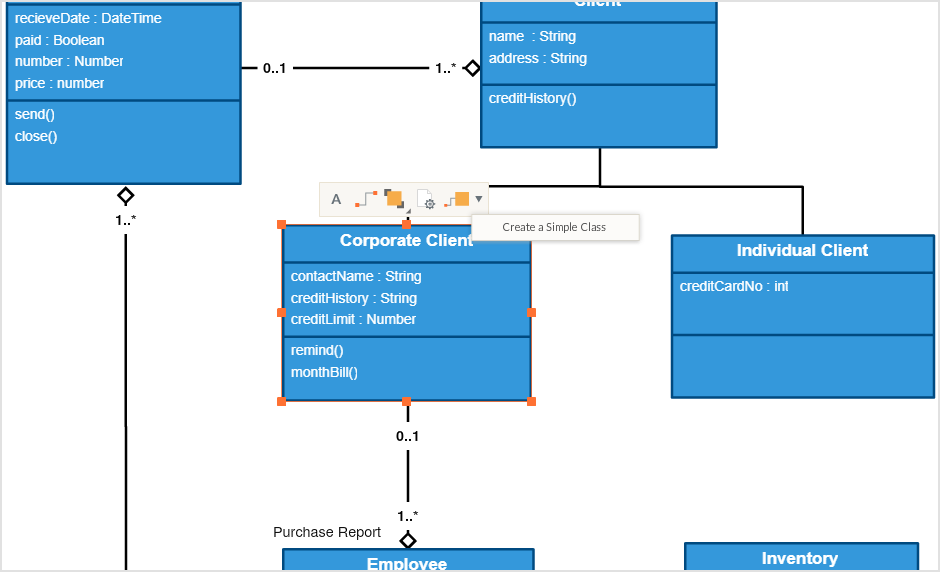
The OMG is best recognized for the Common Object Request Broker Architecture (CORBA) standards. In these diagrams, classes are depicted as boxes, each containing three compartments for the class name, attributes, and methods. Lines connecting classes illustrate associations, showing relationships such as one-to-one or one-to-many.
Have clear documentation of workflow
And the center is the Use Case view which connects all these four. Familiarize yourself with the UML vocabulary, with this list culled from the UML 2.4.1 document intended to help OMG non-members understand commonly used terms. If you are not a fan of those definition stuff, take a look at the following UML diagram examples. I believe that you will understand their differences in seconds.

Lucidchart makes it easy to draw UML diagrams
As the name suggests, a package diagram shows the dependencies between different packages in a system. Check out this wiki article to learn more about the dependencies and elements found in package diagrams. These diagrams are mostly used to visualize software systems because they easily portray the top-level structure. As the name suggests, a package diagram is used to show the dependencies and relationships between packages in a system.
UMass Lowell NERVE Center and Partners Celebrate Decade of Advanced Robotics Design and Discovery - UMass Lowell
UMass Lowell NERVE Center and Partners Celebrate Decade of Advanced Robotics Design and Discovery.
Posted: Mon, 13 Feb 2023 08:00:00 GMT [source]
Ready to collaborate, present, and share
Simply put, if you need a way to visualize and plan your software development process, a UML diagram is incredibly helpful. A deployment diagram models the physical deployment and structure of hardware components. Deployment diagrams demonstrate where and how the components of a system will operate in conjunction with each other. It is analogous to the blueprints used in other fields, and consists of different types of diagrams.
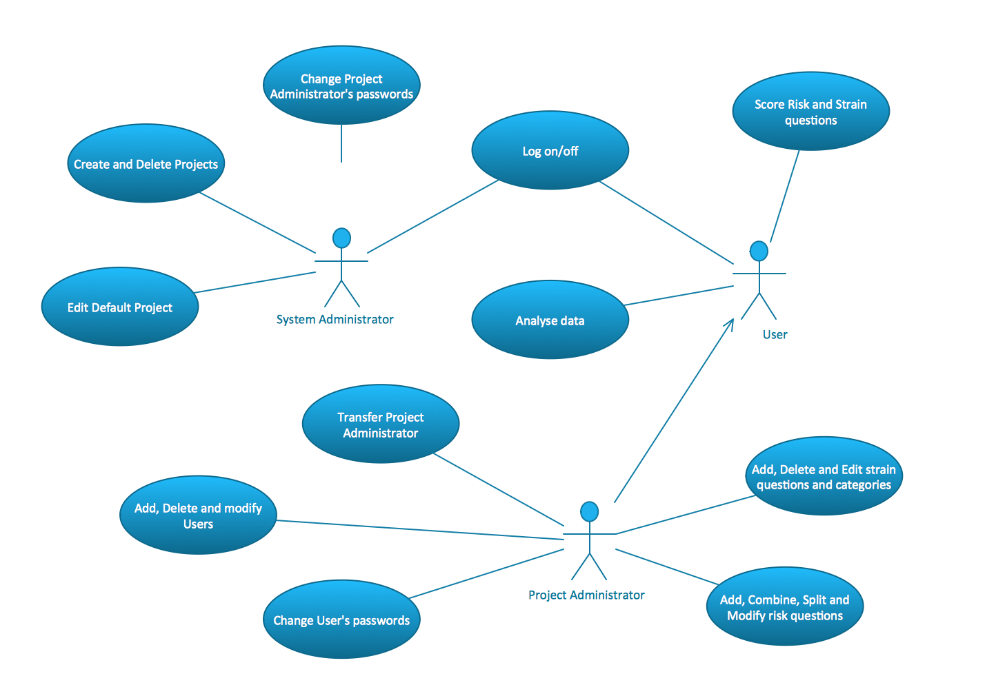
What is a Use Case Diagram?
UML is not a programming language but there are tools that can be used to generate code in various languages using UML diagrams. UML has a direct relation with object-oriented analysis and design. SmartDraw has an extension to generate UML class diagrams automatically using a GitHub repo or a local repository. Learn more about how to build a class diagram without drawing at all using SmartDraw's Class Diagram Extension. Class diagrams are perhaps one of the most common UML diagrams used and class diagram symbols center around defining attributes of a class.
You can also define and visualize the tagged values of stereotypes. The package diagram is a UML structure diagram that shows packages and dependencies between the packages. Model diagrams allow showing different views of a system, for example, as multi-layered (aka multi-tiered) application – multi-layered application model. Class diagrams are the most popular UML diagrams used by the object-oriented community.
New and Improved Buses Rolling Out on Campus this Fall - UMass Lowell
New and Improved Buses Rolling Out on Campus this Fall.
Posted: Wed, 07 Sep 2022 11:43:24 GMT [source]
A static object diagram is an instance of a class diagram; it shows a snapshot of the detailed state of a system at a point in time. The difference is that a class diagram represents an abstract model consisting of classes and their relationships. However, an object diagram represents an instance at a particular moment, which is concrete in nature. The use of object diagrams is fairly limited, namely to show examples of data structure. UML has applications beyond software development, such as process flow in manufacturing. It is the building block of all object oriented software systems.
A composite structure is a set of interconnected elements that collaborate at runtime to achieve some purpose. Class diagrams provide a high-level overview of a system’s design, helping to communicate and document the structure of the software. They are a fundamental tool in object-oriented design and play a crucial role in the software development lifecycle. Communication diagrams are similar to sequence diagrams, but the focus is on messages passed between objects. The same information can be represented using a sequence diagram and different objects. Object Diagrams, sometimes referred to as Instance diagrams are very similar to class diagrams.
Suggested Degree Pathway for Industrial Engineering
We use class diagrams to depict the static structure of a system by showing system’s classes, their methods and attributes. Class diagrams also help us identify relationship between different classes or objects. You've got a great idea for a new app or software feature—but first, you need to show your boss or investors what you have in mind. With a unified modeling language (UML) diagram, you can map out complex systems in a visual shorthand that’s easy to follow. UML diagrams give you a framework to document technical details, from object-oriented software to process workflows—and make them easy to understand, even for non-technical audiences.
Since object diagrams depict behaviour when objects have been instantiated, we are able to study the behaviour of the system at a particular instant. The Object Management Group (OMG) is an association of several companies that controls the open standard UML. The OMG was established to build an open standard that mainly supports the interoperability of object-oriented systems. It is not restricted within the boundaries, but it can also be utilized for modeling the non-software systems.
Our Boardof Directors includes prominent and influential members who act asvisionaries who shape the direction of the organization. Having a flow chart can help visually represent actions or people in a complex situation. Identify the actors that use a system, and show how they interact with it. For example, an online ordering system might engage new and existing customers, a procurement manager, customer service agent, and AI chatbot. Use case diagrams also look at internal and external factors that influence functionality. Component diagrams are used to describe the static deployment view of a system.
I handle marketing stuff here at Creately including writing blog posts and handling social media accounts. It’s easy to share your diagram with other users and external stakeholders, and you can even customize your diagram to meet your requirements. To try Miro, all you have to do is sign up for free, choose a template, and you’re good to go.
The Three Amigos published The Unified Modeling Language User Guide in 1999, and an update which includes information about UML 2.0 in the 2005 Second Edition. A profile diagram enables you to create domain and platform specific stereotypes and define the relationships between them. You can also define and visualize tagged values of stereotypes. An Object Diagram can be referred to as a screenshot of the instances in a system and the relationship that exists between them.
Because there is data available in the objects, they are used to explain complex relationships between objects. In a more technical term, they show different objects in a system. They describe how the objects interact with each other to create a functioning system. By now, you’ve got a pretty solid understanding of how to create a UML diagram. Object diagrams show the attributes of each object in a system and how those objects relate to one another at a specific time.